![]()
![]()
![]()
![]()
![]()
copyright
(c) 2000-2009
mode zero
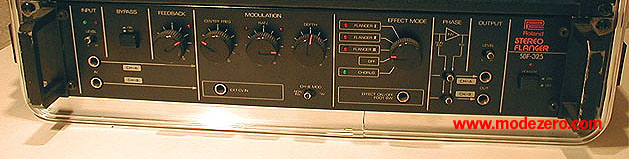
roland sbf-325 stereo flanger / chorus
the facts The Roland SBF-325 is an analog stereo flanger which was in production from 1979 to 1986. In 1986 the list price was $525, the same price as the SPH-323 rackmount phaser in the same series. Currently, a used SBF-325 can cost anywhere from $200-600 depending on seller and condition. The signal path of the 325 is true stereo in and out, which is unusual in analog flangers. There are duplicate front and rear stereo 1/4" inputs and outputs. Input and output each have a high/low level switch, green signal LED, and red peak LED. Two additional front panel 1/4" jacks are for remote effect switching and external control voltage input. There are no XLR connections. The two areas where the 325 is most impressive are the quality of the analog flanging sound itself and the amount of flexibility. The four leftmost knobs are what you would expect on a full-featured flanger: feedback, center frequency, modulation rate, and modulation depth. To the right of the four control pots, the Effect Mode switch selects one of three flanger modes, one chorus mode, or off. There are also three invert switches which combine with the other controls to give the analog equivalent of several distinct flanging "algorithms."
For demonstration, two test samples, an Oberheim Matrix-1000 pad (m1000) and a sample-CD sustained guitar chord (gtr), were run through the SBF-325 at a number of different settings, both moderate and extreme. The dry samples (16 bit / 44.1k) were played back from an Akai S2800 sampler directly into the inputs of the flanger. No envelopes, filters, or effects were used in the S2800. The output of the flanger was recorded directly to a DMAN PCI stereo sounds card (16 bit / 44.1k) in a Pentium PC. The resulting wav files were encoded as 128 kbps mp3 files using AudioCatalyst. For reference, here are dry versions of the samples that were used for demoing: dry Oberheim Matrix-1000 analog
synthesizer pad dry sustained distortion
guitar chord
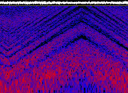
the sounds Here's pink noise processed through one channel of the 325 on a typical setting, with a spectrogram of the same sound (increasing time is to the right, increasing frequency is up (logarithmic), low to medium to high amplitude = black to blue to red):
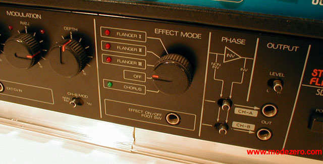
Flanger mode I sums the inputs and generates a mono flanged output. This is a good traditional resonant flanger sound. mode I, fb = 8, ctr freq
= 5, rate = 4, depth = max, nothing inverted Here's the same sound and the same settings, but using mode II, which is true stereo flanging. Even though the m1000 sample is mono, the 325 is generating a stereo image. Most likely the delay time on each channel is slightly different, creating the stereo effect. mode II, fb = 8, ctr
freq = 5, rate = 4, depth = max, nothing inverted Mode III is cross-feed stereo, i.e. the output of each delay line is fed back into the input of the other delay line. This is a unique flanging sound, especially at high feedback settings. Mode III is mentioned by Roland as the inspiration for the digitally modeled "analog flanger" effect in their recent grooveboxes. mode III, fb = 8, ctr
freq = 5, rate = 4, depth = max, nothing inverted Next to the Effect Mode section, two switches in the Phase section allow either or both of the delayed signals to be inverted before being mixed with the dry signal to produce flanging. Usually, both channels are inverted or not, but occasionally you can get some unique flanging by only inverting one channel. In addition, a switch in the Modulation section causes the modulation waveform to be inverted on channel B, producing stereo panning effects. Here's an example that's identical to the mode II example above, but with the phase inverted on both channels and the modulation inverted on channel B, for a cutting, panning flange. m1000: mode II, fb = 8,
ctr freq = 5, rate = 4, depth = max, everything inverted The same except using mode III gives a less airy, more midrangey effect: m1000: mode III, fb = 8,
ctr freq = 5, rate = 4, depth = max, everything inverted By reducing the modulation depth to 5 and setting the center frequency to minimum, and with everything inverted, we start to get into "psycho drainpipe" territory. m1000: mode III, fb = 8,
ctr freq = 0, rate = 4, depth = 5, everything inverted All of the examples so far have been at moderately high resonance settings. The 325 also sounds great at more "table-trained" settings. Here the feedback is zero but using different combinations of the invert switches and mode III gives beautiful wide spatial effects. m1000: mode III, fb =08,
ctr freq = 4, rate = 6, depth = max, A-, B+ m1000: mode III, fb =08,
ctr freq = 4, rate = 6, depth = max, A-, B+, B mod- Here's a sustained guitar chord sample through the 325 with some knob twiddling: This is the same guitar sample but using an external triangle LFO to control the 325's delay lines. When a control voltage source is plugged into the Ext CV In jack, the Depth control scales the cv input and the Center Freq control adds an offset. This sample demonstrates how the external cv source allows you to push the 325 into extended delay times which you can't access from the internal LFO. Be careful -- beyond a certain point, the flanger will start emitting clicks, cyclic noise bursts, and thumps, depending on which parameter of polite flanging you've exceeded. But just short of this, there's a nice "psycho drainpipe squared" region, and of course, using the external LFO you have more controls to play with. In this case, I used the longest delay time obtainable in mode III without delay line aliasing or noise, lots of feedback, then manually adjusted the speed of the external LFO as the sample played. Other possibilites include using a cv pedal or a midi/cv converter. gtr: mode III, fb = 8, ctr
freq = 0, rate = 5, depth = 3, everything inverted The chorus mode of the SBF-325, which uses the Modulation section's Rate and Depth controls as in the flanger modes, is nice, but it's more of a chorus/flange sound than a true "Roland chorus." The feedback control is not available in chorus mode. This sample uses moderate settings for Rate, Depth, and Center Frequency. When using modulation, the effect of the Center Frequency control is more subtle than in the flanger modes. m1000: chorus, fb = 0,
ctr freq = 5, rate = 5, depth = 5, nothing inverted However, one useful trick that can be done in chorus mode is to set Rate and Depth to zero, then sweep the Center Frequency manually. A distinct back and forth panning effect can be heard as the Center Frequency is manually turned from min to max. Leaving the Center Frequency in a fixed position gives a very useful double-tracking effect which is less obvious than LFO chorusing. m1000: mode III, fb = 0,
ctr freq = manual, rate = 0, depth = 0, nothing inverted
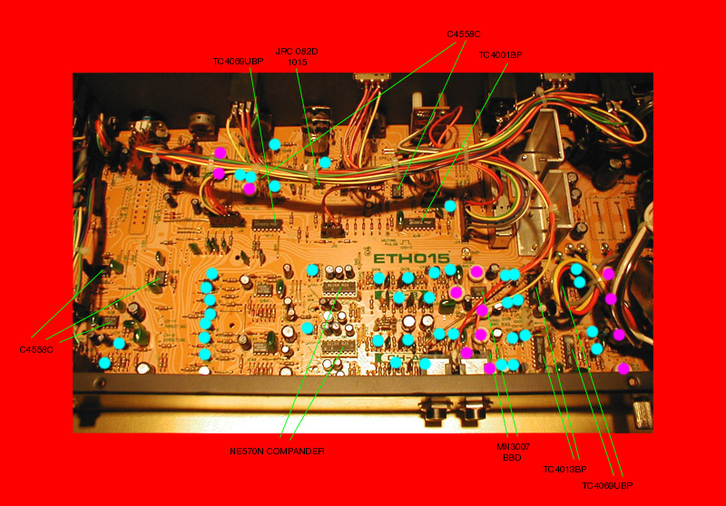
the guts Taking the SBF-325 apart requires, at a minimum, unscrewing the rack ears and removing the screws on the underside of the case. The front panel does not need to be removed unless you need access to the pots. Once the case is slid off backwards, the single large circuit board can be seen. It is very cleanly laid out, with many components laid out in parallel for the A and B channels as you would expect. The key chips are the dual NE570N companders and dual MN3007 bucket-brigade delay lines. The companders are the only socketed chips. There are many trimmers for everything from feedback volume to LFO parameters. The board is very well marked with points where clock signals, LFO waveforms, etc. may be measured. In the picture below, the discrete transistors are marked with blue dots, while trimmers are in purple. The power supply is the area at upper right, to the right of the two thick vertical metal shields. Note that we're looking at the box upside down, i.e. these components would normally be facing downwards while in operation.
|